This is a page that I will use to document my progress working on the robot that I'm going to enter into the robotics expo 2003 (April 2003). Yeah, I know its quite an outrageous head start, but I've decided to make this event an independent study for college credit going to my EE degree.
I have entered this competition before with a friend. Actually, he did more than 90% of the work but I learned a whole lot from the experience and plan to keep engaging in this madness for many years to come. If you're curious, click on the following banner to see what we did for robo 02:

July 20 02 - At the top of this webpage, there is a picture of the first design concept model. Plywood, metal ground cover stakes, toilet paper rolls, bicycle tube and plastic straws. Completely non-functional, but it was fun to get out the band saw and hack away at it. Also, having a physical object helps to get my brain thinking about how to approach this challenge.
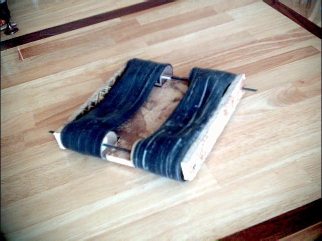
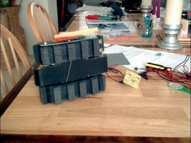
Aug 1 02 - Anyways, where to begin? What you see just below this paragraph is my first real attempt at the robot. I took some aluminum sheets from an old HP3060 and forged a chassis that worked pretty well but was too long to make turning feasible. The treads were made from ordinary bicycle tire with little spongy door seal (cut to 2" length each) that self-adhered pretty well to the rubber. I thought that I was going to need to rubber cement them on there or something but they held pretty well. I used office staples to link one end of the tread to the other. That worked pretty well too, also kept the weight down.
Aug 2 02 - Scrapped the old chassis since its length put too much stress on the motors and made one that was 7 centimeters shorter. Now it is a perfect square and has a remarkable turning responsiveness. Also used coat buttons to connect the treads, but they sometimes pop off after about a minute or so of maneuvering.
Also, made an undercarriage where the battery will rest and help shield the two motors from obstacles. Looks very nice too.
Aug 18 02 - Placed the robot on our 30 degree ramp (emulated to the dimensions of robo 02 and noticed that the rollers and the treads have a lack of friction problem. Added some little pins to the rollers (about three each at 120 degrees from each other) and that seems to take care of the problem very well.
Aug 26 02 - Today school began. Submitted my proposal for independent study to CSU, but it seems like I'm almost halfway there already. Sheesh.
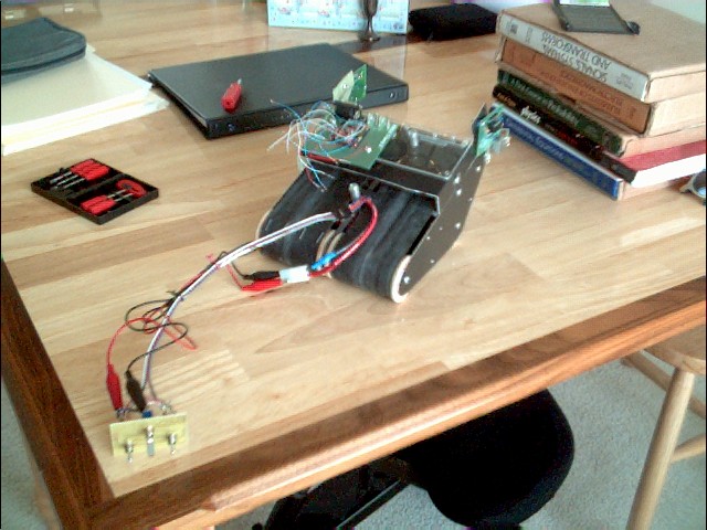
Aug 30 02 - Made a tester for the Infra Red Proximity Detectors (IRPDs) which will detect pitfalls. Seems like they don't work worth a crap... very intermittent. But I've decided to go ahead and mount them on the robot anyway for some truly useful emperical data. I have a feeling they might not be reliable enough though.
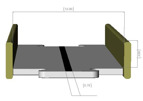
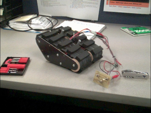
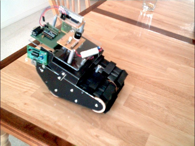
Sept 15 02 - Finally cracked out a chassis and four wheels for version 3.0. Beauty, eh? I really like the aggressive profile and the larger tank-like 'angle of attack' in the front. Those treads shouldn't have too much difficulty overcoming the sea of bolts, but only time will tell. The width of the treads are 3" instead of the modest 1.5" as before so as to increase surface contact. One may notice that there's little or nothing between the two treads to get stuck on. The two pairwise 'free rollers' will be in the front and are made from balsa wood, hard board and toilet paper roll cylinders. I'm doubting the structural integrity of those paper towel rolls, but just like with those lousy IRPDs, I'm going to give it a go anyway.
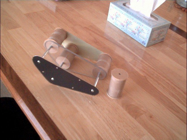
Sept 22 02 - Mounted the drive rollers in the front. Took some wooden cylinders and milled out a hole lengthwise just the right size for some aluminum tubing to friction fit inside. They slide perfectly over the 1/4" alloy axle and spin freely with no play whatsoever. Excellent. Over the wooden cylinders, there fits a pair of rubber rollers from an old Epson dot matrix printer. Lots of happy coincidences to get everything to fit perfectly.
Once I finished that feat with surprisingly little effort, I milled out a square inside the middle lexan stabilizing chassis so that I could fit the battery through on top of a support plate which also functions as the bottom tread slider.
Next step is to mount the engines on a second piece of lexan and install a chain that I'm going to purchase from McMaster-Carr.
I also made some treads from a couple of old mousepads, instead of bicycle tubes as before. They're much more spongy and stretchable. No need for snap on buttons since they slip onto the robot fairly easily. We'll see how durable they are when it comes time to field test.
Sept 29 02 - McMaster-Carr had a wonderful assortment of goodies to order from. The chain that I ordered is made of Acetal and is self-lubricating. Also, you can take it apart and put it back together again without any special tools. Two feet cost me $22.66 and I got it two days after ordering.
The unfortunate thing is that the sprockets would have cost me about $15.00 each, which meant another $60.00 total for the four of them. So, I figgered I'd go ahead and make my own by drilling holes around the outside of the wooden cylinders and tightly fitting snipped toothpicks inside the holes. With a little line of toothpick stubs sticking out all around the cylinders, the end result looks like a crude contraption from Gilligan's Island. Initially they didn't work too smoothly, but after a little whittling, filing and re-shaping of the stubs, they seem to fit the chain pretty nicely.
Made a square Lexan cross beam on which the motors are now mounted. It's squarely half-flapped with the other piece of Lexan which runs lengthwise to the robot. The nice thing about these motors is that they can be mounted a number of different ways. Their output shafts were easily shortened so that they could both fit inside the cavity of the hull. Quite versatile.
So, Phase I (hardware and locomotion) is almost complete. Just need to finish those treads and mount a canopy for the sensors (Phase II - sensors and electronics) and other programmable circuits (Phase III, software). What great fun this is...
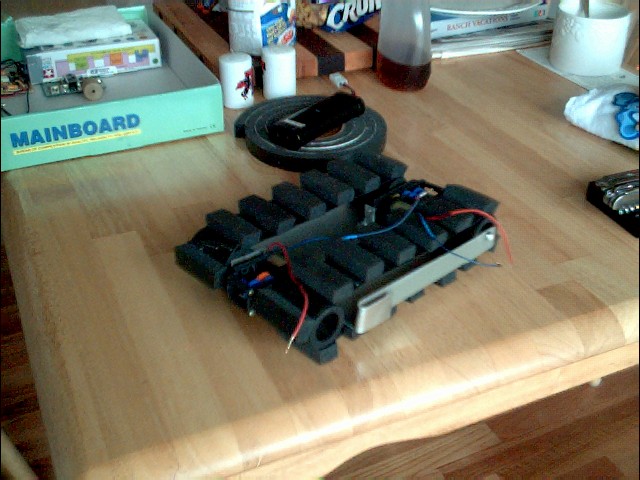
Oct 06 02 - Didn't make much progress this week. Just built some new treads out of bicycle tire tubes, made a canopy and mounted the Programmable Logic Controller (PLC) with a couple of the sensors.
Found that if I make the rubber tube treads tighter than usual (like with the spongy stuff), they'll perform much better. I used staples again to link the ends together.
The canopy mounts all the circuits as well as the sensors. The IRPDs are aimed straight down and to the front of the robot. I will need to fine tune them to detect both pits and walls. I may abandon the mechanical sensor idea and just keep things simple by using only the IRPDs. This means that I may end up having to buy a more advanced and reliable set of sensors.
Designing modular parts is going to be essential for effeciently completing this project. I'm hoping to design something that is going to be easy to disassemble and reassemble. Don't want to pull the whole thing apart if I just need to make a small adjustment somewhere inside.
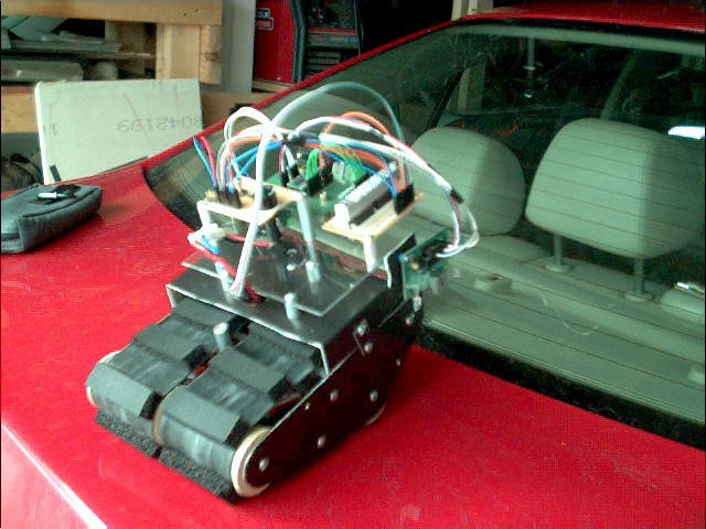
Oct 13 02 - Rebuilt one of the front rollers since it was getting stuck every so often and I yoinked some parts off of last year's bot (the linear 5V regulator, in particular). Also mounted some more stuff onto the canopy (not pictured - its a surprise for next week!).
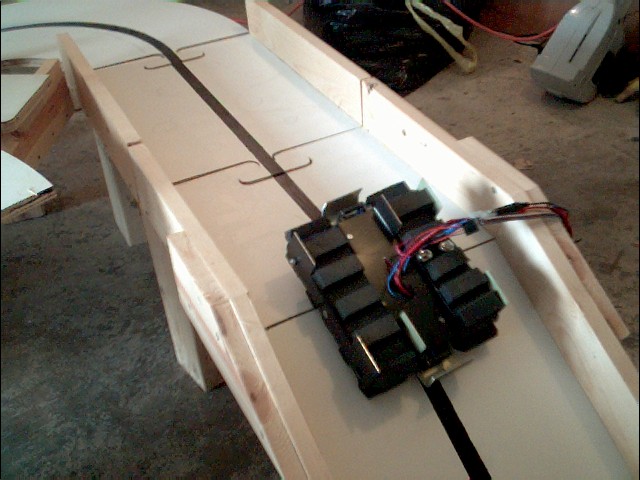
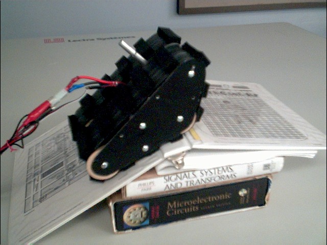
At last! The notebook incline test was very successful. This guy can climb anything less than 35 degrees! It also turns quite nicely.
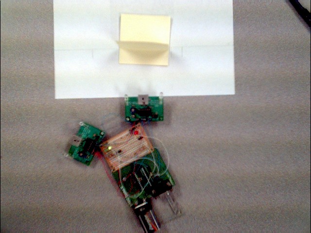
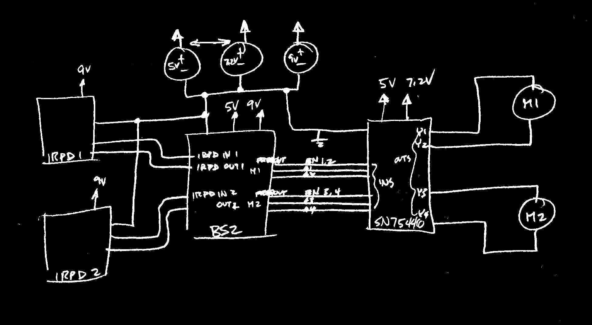
I purchased the very nice half-H bridge driver SN754410 which will directly make the engines go. It should be arriving any day now. So, here's a very overhead view of how the circuits are going to be connected:
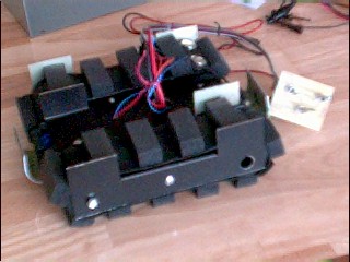
Oct 20 02 - The H-bridge motor drivers have arrived! I spent this entire morning wire-wrapping both of them. In theory, I just need one, but given the current needs of the motors, I'm putting them both in parallel and affixing a custom-made heat sink on top of them just to be on the safe side (these guys get REAL hot if you're not careful). All that remains of Phase II is the final wiring and then its on to programming.
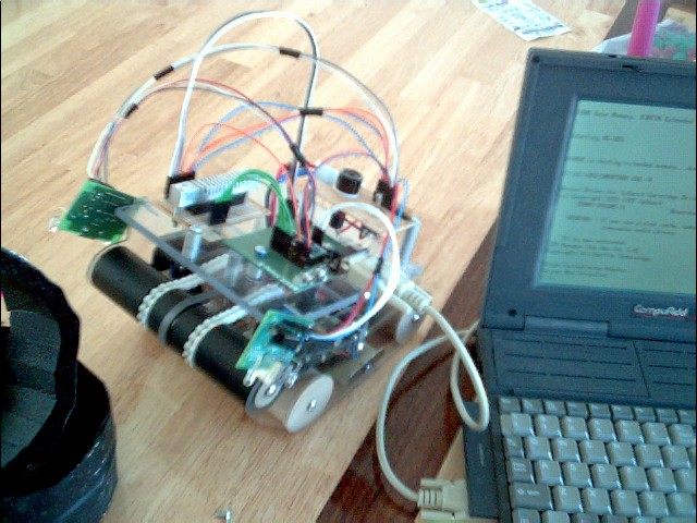
Nov 10 02 - It's ALIVE!! Finished the wiring and started programming the PLC. Had a few preliminary stumbling blocks, but in the end, got the PLC to integrate with the line drivers and it went forward! That's all I had time to do really. Next week, I'll try to get the sensors to start working too.
Nov 30 02 - Been awhile since I worked on the old bot. Changed out the canopy plate and replaced the side ferrings with lexan. Now the robot looks completely transparent. Kinda neat. To add stability, I doubled the tread count on both sides and now it rolls very smoothly. There is a problem however with the gilligan gears that are attached to the rollers. Apparently they like to slip a little too often. Replacing them with real gears is going to be quite an expense (at $15 a sprocket, ouch!).
Those sensors aren't quite where its at. I may have to add some proximity measuring devices on the sides to compensate for their poor performance. Once again, that's going to be a lot of work. So right now, I'm not sure if I'm going to work on it anymore until after Xmas.
Click on the following graphic to go to Robot Expo 2003: